
What is Formula Student?
Formula Student is an international engineering design competition run by the Institution of Mechanical Engineers, where university teams design, build, and race a single-seat open-wheel racing car from scratch. Teams compete across a series of static and dynamic events that together test not just the car, but the engineering rigour behind every decision that shapes it.
The points split matters more than most people realise. Of the 1000 total, 325 points are awarded across the static events alone - design is worth 150, cost 100, and business presentation 75. The dynamic events split the remaining 675 between acceleration (75), skidpan (75), autocross (100), and the flagship endurance and efficiency event (425 combined). What this means in practice is that a team that builds a genuinely fast car but cannot explain it to the design judges is leaving nearly a third of the available points on the table before a wheel has turned.
The design event is arguably the most intellectually demanding part of the competition. A panel of industry judges - many of them working chassis, suspension, and vehicle dynamics engineers at OEMs and motorsport organisations - dissect every engineering choice in the car. They are not interested in whether it looks fast; they want to know why you chose that spring rate, what your load transfer analysis tells you, and how you validated your choices. For a suspension engineer specifically, it is as close as you get as a student to a genuine engineering design review.
"The fastest setup is worthless if you can't explain why it works."
- Paraphrased from Milliken & Milliken, Race Car Vehicle Dynamics (1995)Why it matters for an aspiring vehicle dynamics engineer
Most undergraduate engineering projects involve analysis of an existing system, or design of a single component in isolation. Formula Student is different in one crucial respect: you own the full lifecycle. The suspension on this car starts as an idea rooted in vehicle dynamics theory, gets developed through analytical tools I am building myself, refined through simulation, translated into manufactured components, and will ultimately be validated through physical testing on track. That complete chain - from first principles to physical evidence - is rare at undergraduate level, and it is exactly the kind of work that translates directly to industry roles in vehicle dynamics, chassis engineering, and motorsport.
There is also the constraint-driven nature of the work. Industry does not hand you unconstrained design freedom, and neither does Formula Student. Packaging envelopes, regulatory compliance, manufacturing capability, weight targets, and budget all push back against the ideal solution. Learning to navigate that - to make defensible engineering trade-offs rather than just optimising a single variable - is the real education.
The project in context
This project concerns the suspension system for Team HARE's 2026 car. The suspension system is the interface between the tyre and the chassis, and its job is to keep as much of each tyre's contact patch pressed against the road as possible, in as many conditions as possible. More contact patch means more grip, more cornering speed, harder braking, and faster acceleration.
But the fastest car on paper is not always the fastest car in practice. As Milliken & Milliken note in Race Car Vehicle Dynamics, a suspension system set up perfectly for a theoretical ideal driver may be genuinely difficult to drive at the limit. So the design target is not just peak grip - it is a system with enough independent tunability that we can shape the car's behaviour around the driver. That is the core motivation for mode decoupling.
The body modes - and why decoupling them matters
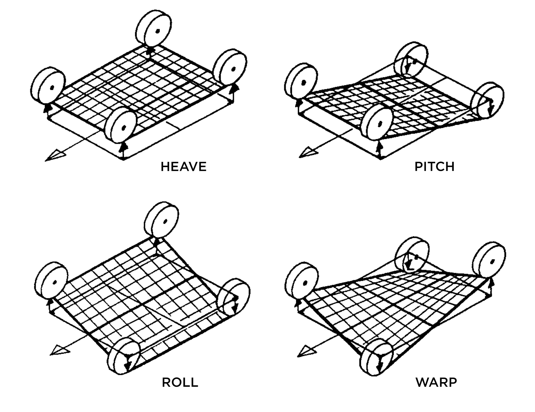
A car's body moves in four principal ways relative to its wheels, each governed by different physical mechanisms and each affecting vehicle behaviour in distinct ways. This framework is set out clearly by Milliken & Milliken and Olley in Chassis Design: Principles and Analysis.
In a conventional spring-and-damper suspension, these modes are inherently coupled - changing the spring rate to stiffen heave also changes roll stiffness, and adjusting roll stiffness via springs affects ride frequency. Mode decoupling breaks these dependencies apart. For Team HARE's low-downforce car, the meaningful gains are in decoupling roll from pitch stiffness via ARBs, rather than investing in a full heave decoupling system that would add mass and complexity for limited return.
Choosing the architecture - double wishbone
The double wishbone configuration emerges as the clear choice after reviewing the alternatives. It offers precise kinematic control over camber gain, roll centre height, and instant centre location - all tunable through hardpoint placement. As Theander demonstrates in Design of a Suspension for a Formula Student Race Car, the inboard rocker layout allows springs, dampers, and ARB pickup points to be positioned centrally, keeping unsprung mass low and the centre of gravity close to the floor. This aligns directly with the theoretical frameworks of Milliken, Olley, and Pacejka - and it is the dominant architecture in Formula Student for good reason.
Reviewing existing decoupling approaches
Simulation methodology
Rather than jumping straight into CAD, the plan is to build up a layered simulation framework. Each layer adds fidelity and is cross-validated against the one below it before adding complexity.
Every project needs a solid foundation, so the first few weeks are spent deep in the literature. The usual suspects are on the reading list - Milliken & Milliken, Gillespie, Pacejka - alongside more niche references like Theander's Formula Student suspension design thesis. It is the kind of reading that takes time but pays back tenfold later.
Rather than jumping straight into CAD, the focus here is on building the analytical infrastructure - the tools that underpin every design decision downstream. It is a productive sprint, and some of the outputs end up being useful well beyond this project.
The centrepiece is a comprehensive Excel suspension geometry tool. Feed in the hardpoints, and it outputs dynamic properties, tyre stiffnesses, spring rates, motion ratios, anti-roll bar characteristics, and wishbone lengths. On top of that: a MATLAB data analysis GUI for processing MoTeC telemetry from the car's dashboard (now used across teams), a G-G diagram tool for visualising lateral and longitudinal acceleration and understanding load transfer, and a Pacejka 5 regression tool using Tyre Test Consortium data - the latter feeding directly into Adams Car modelling later.
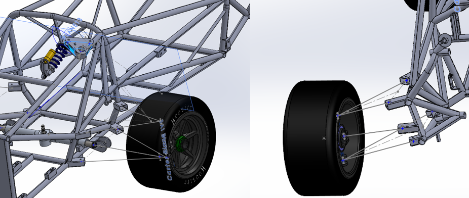
Early CAD work begins in parallel, mostly to understand rocker positions and think through the chassis changes that will be needed. ARB specification is also started. The design machine is warming up.
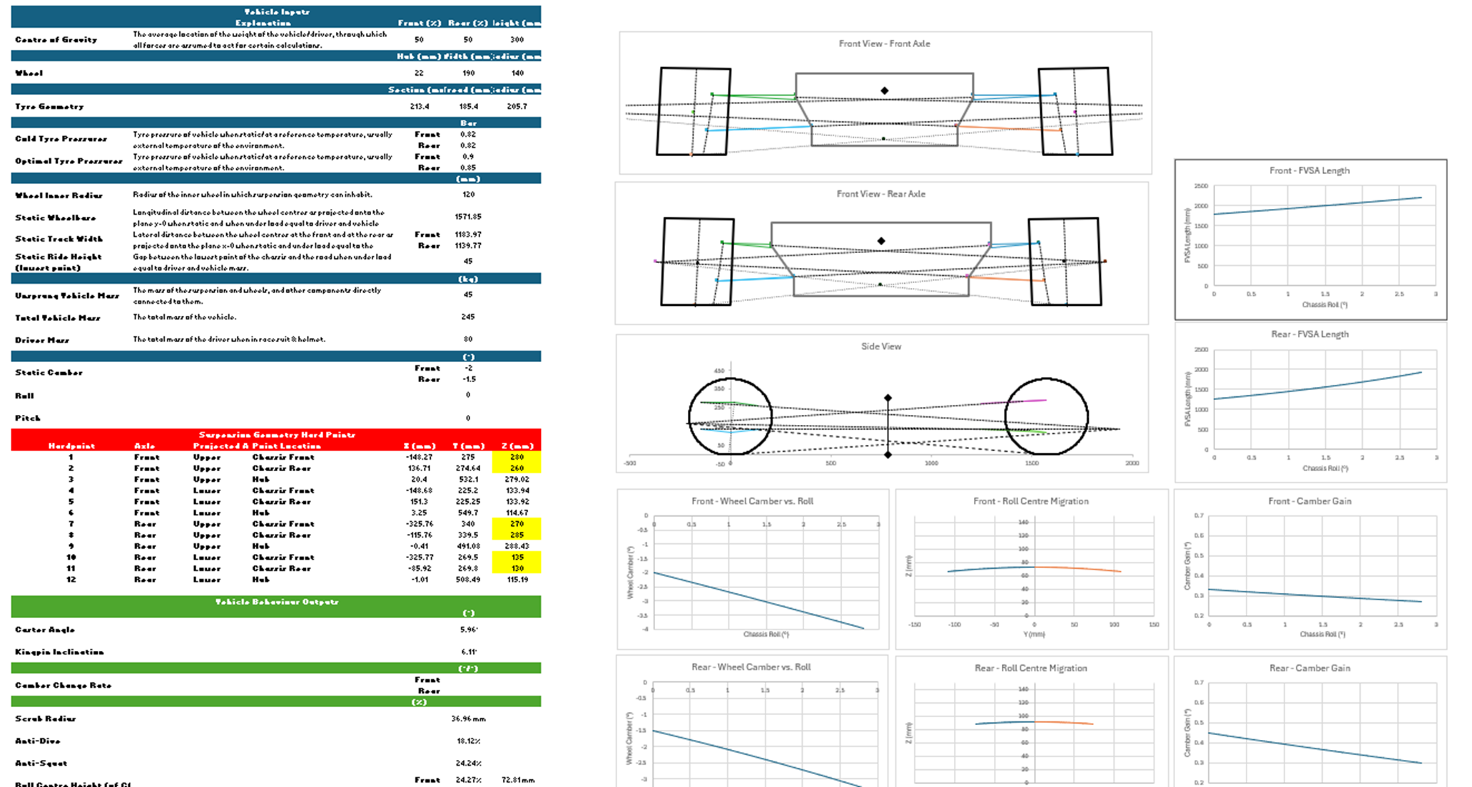
The initial front and rear suspension designs are now done - geometrically fixed, with spring rates and ride frequencies calculated. The big remaining task is translating geometry into actual components, but the hard thinking about where everything lives is settled.
Rockers are sized based on motion ratios and pushrod angles, and the ARB specification work begins in earnest - though an early error (calculating springs in series rather than parallel) means those numbers need to be revisited. A useful reminder that first-pass calculations always need a sanity check.
The to-do list at this stage is substantial: ARB design, force calculations across all components, full component design (wishbones, pushrods, rockers, toe links, steering arms, ARB links and arms, diff hanger brace), FEA, drawings, manufacture, Adams modelling, tube testing, and track validation. A long road ahead, but the path is clear.
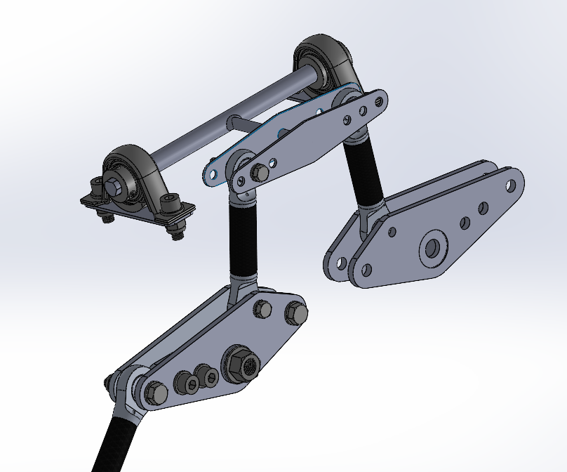
One thing is clear this fortnight: ARB specification takes far longer than anticipated. It always does. The material choice lands on 4130 chromoly steel - good availability, well-understood fatigue behaviour, and weldable. A supplier is sourced.
Target diameters come out at 10 mm front and rear for ideal roll stiffnesses, with a high-level CAD model started to house everything. FEA on the chassis mounts is flagged as upcoming work, with the key question being how to correctly define the worst-case load - not just spring rate times maximum travel, but accounting for suspension bottoming-out scenarios.
Progress is slower than ideal here, but getting the ARB specification right is genuinely important - it is the primary roll stiffness tuning mechanism for the whole car, so it is worth the time.
A satisfying update: full part design hits approximately 95% completion. Pushrods, wishbones, rockers, and roll bars are all done in CAD form. The rear ARB is converted from a U-bar to a T-bar configuration - a better packaging solution that also saves some weight. Front and rear rockers are redesigned for improved packaging while keeping the same geometry.
Bearing specification is complete. The ARB diameters are revised: 5/16 in. at the rear, 10 mm at the front - a small but meaningful change from the earlier iteration.
Remaining work: toe links, part mirroring, FEA of nodes and bars, and production drawings for all in-house manufactured components. A manufacturing team meeting is on the calendar for the end of the week.
The focus shifts here from design to getting parts actually made. Two components (and their mirrors) are changed following manufacturing team feedback - a necessary but slightly humbling step that comes with every real engineering project.
Material selections are finalised: Aluminium 7075-T6 for most nodes and structural linkages, 6082 for non-load-bearing parts where lower cost and slight weight saving make sense, and 4130 steel for anything welded. DIN ISO 286 press-fit tolerances are applied across bearing interfaces.
The model is populated with fixtures and fittings, material and component orders are initiated (CFRP tubes, aluminium, steel, adhesives), and the first production drawings start flowing out. With 80 individual machined parts and 48 assemblies to track, keeping on top of the logistics becomes a project in itself.
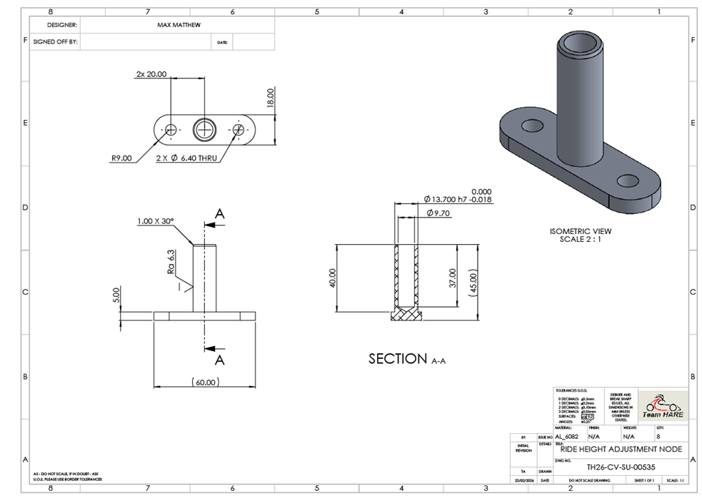
Design freeze. 37 parts and 2 welded assemblies are drawn, toleranced to DIN ISO 286, and approved by manufacturing. A significant milestone.
FEA is carried out on nodes and rocker assemblies, specifically to investigate whether parts can be downgraded from 7075-T6 to 6082-T6 aluminium (simulated as 6063-T6 in SolidWorks, which is functionally equivalent). The headline result: almost everything passes comfortably. The one exception is a stress concentration at the bearing interaction point of the worst-case node - but this is an artefact of modelling a bearing as a fixed point rather than a pivot. In reality, the plain spherical bearing allows rotation, so that "stretching" mode does not physically occur. All other regions on that node sit around 90 MPa, giving a factor of safety above 2.7 against 6082's yield strength.
The rocker FEA tells a more relaxed story: 0.1 mm deflection, under 10 MPa, FOS above 25. There is weight to be saved on the rocker plates, but given each one is about 20 g, the return on further iteration is judged to be minimal.
Material orders are placed, CFRP tube testing is scoped (axial compression, tension, and bending, with node overlap length as a variable), and the rear ARB receives a small geometry tweak to clear a clash at high bump/droop.
An honest assessment: a slower couple of weeks. The bulk of the effort goes into updating models for manufacturability - the kind of detail work that does not feel dramatic but is genuinely important for making sure the parts come out right. Material arrives and further FEA is performed.
Work begins on the design of a test fixture for node and tube compression, tension, and bending tests - varying both node-to-tube overlap lengths and CFRP wall thicknesses. This is important validation work: understanding the actual failure modes of the bonded carbon assemblies will either confirm the 40 mm overlap as conservative (likely) or flag a problem before the car is loaded.
Adams Car simulation of both the 2021 and 2026 suspension layouts is queued - a critical step for comparing predicted dynamic behaviour and validating the design targets set at the start of the project.
Outstanding: cone washer modelling, bolt specification, steel chassis mount drawings, node/tube testing, and Adams Car validation. The finish line is in sight.